CAN Bus Error Code: Diagnosis, Fixes, and Prevention
Urgent guide to understanding CAN bus error codes, diagnosing symptoms, and applying safe fixes. Learn quick checks, diagnostic flow, and when to call a professional.

A CAN bus error code signals a fault on the Controller Area Network, interrupting message transmission between ECUs. It often points to wiring problems, faulty connectors, poor termination, or a misconfigured baud rate. The fastest route to a fix is to verify physical layer integrity, correct termination, and node addresses, then re-test with a controlled diagnostic session.
What a CAN bus error code means in practice
A CAN bus error code doesn't just flash on a screen; it signals a fault in the Controller Area Network that connects multiple ECUs in automotive or industrial systems. When a fault is detected, the network may drop frames, duplicate IDs, or exhibit intermittent messages, leading to degraded performance or complete loss of critical communications. In urgent scenarios, engineers treat CAN bus error codes as high-priority alarms that demand immediate triage. The root cause is often a combination of physical layer issues (wiring, connectors, grounding), incorrect termination, or misconfigured baud rates, followed by software-level misbehavior in one or more ECUs. As you begin troubleshooting, isolate the physical layer first, then verify node configuration to narrow down the fault quickly. This approach aligns with the goals of Why Error Code: rapid identification, minimal downtime, and safe repair practices.
Common sources of CAN bus errors
Common sources of CAN bus errors include:
- Damaged or corroded connectors and harnesses
- Loose or unplugged CAN cables
- Missing or incorrect termination resistors at the ends of the bus
- Baud rate mismatch between ECUs
- Grounding issues causing common-mode noise
- Faulty ECUs that generate invalid messages
- Electrical transients from nearby equipment
In urgent cases, inspect the physical layer before delving into software configuration. Each cause has different remedies; starting with the most probable causes reduces downtime. Understanding these CAN bus error code roots helps you triage from symptom to fix efficiently.
Quick fixes you can try safely
Before diving into deep diagnostics, try these quick fixes to reduce CAN bus error code noise:
- Power down the system and unplug nonessential modules
- Gently reseat all CAN connectors and verify no corrosion
- Verify that the bus is terminated with appropriate resistors at each end
- Check that the most important ECUs have correct addresses
- Reconnect and test after each change
These steps are safe to perform in a lab environment and can restore function in many simple fault scenarios. If issues persist, proceed to the formal diagnostic flow.
Diagnostic flow overview
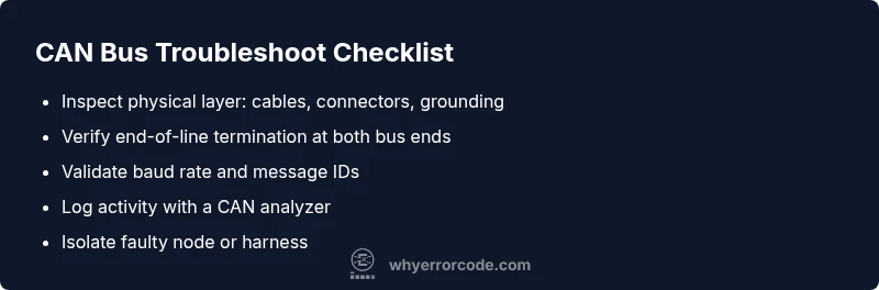
A structured diagnostic flow helps you move from symptom to fix with fewer blind guesses. Start with symptom documentation and log review, then progress to the physical layer checks, followed by live CAN bus analysis with a suitable analyzer. Next, verify termination and baud rate settings, and gradually isolate suspect nodes. The CAN bus error code should guide the path of investigation: priority to the most probable physical-layer faults, then configuration mismatches, then defective ECUs.
Step-by-step repair approach (high-probability path)
In most CAN bus error code cases, hardware faults are more common than software issues. Begin with the following narrative to frame your repair:
- Stage 1: Safety and prep – power down, secure the workspace, and document current configurations.
- Stage 2: Hardware inspection – check cables, connectors, and terminators; look for signs of damage.
- Stage 3: Configuration check – confirm baud rate, bit timing, and IDs across ECUs.
- Stage 4: Node isolation – disconnect nodes one by one while watching CAN traffic.
- Stage 5: Repair or replace – fix wiring, replace damaged connectors, or swap a faulty ECU.
- Stage 6: Verification – re-connect everything and run comprehensive tests to confirm no CAN bus error codes reappear.
Pro tip: perform tests on a bench setup first and keep a change log for future prevention.
Other causes and how to rule them out
If the primary causes do not explain the CAN bus error code, expand the investigation to less likely scenarios. Look for interference from nearby electrical devices, quality of power supply, and grounding paths that introduce noise on the CAN high and CAN low lines. Reproduce the fault in a controlled environment, compare with a known-good baseline, and use a CAN analyzer to correlate frame errors with particular nodes. This systematic approach reduces guesswork and speeds recovery.
Safety, costs, and when to call a professional
Dealing with CAN bus error code faults can involve risks, including electrical short circuits and vehicle safety implications. Always follow safety procedures, disconnect power before handling harnesses, and use proper PPE. Costs vary widely based on location and fault complexity, and a professional diagnostic can provide an accurate quote after a hands-on assessment. If the fault involves high-voltage systems or critical safety channels, consider escalating to a qualified technician immediately.
Prevention and best practices for CAN bus networks
Preventive care minimizes CAN bus error code occurrences. Adopt consistent wiring practices, use shielded cables where appropriate, maintain clean terminations, document ECU configurations, and implement periodic electrical tests. When introducing new nodes, verify compatibility and update timing parameters in a controlled lab. Regular monitoring with a CAN analyzer enables early detection of anomalies before they trigger a fault.
Steps
Estimated time: 45-60 minutes
- 1
Power down and secure workspace
Shut down all power sources and disconnect service power. Ground yourself and disable any active test rigs before touching CAN hardware.
Tip: Label cables before disconnecting to track changes. - 2
Inspect physical layer
Visually inspect CAN cables, connectors, and terminations for damage. Reseat and reseal connectors; replace damaged pins or broken cables as needed.
Tip: Look for pin corrosion and bent terminals. - 3
Verify termination and bus length
Ensure 120-ohm termination resistors are present at the two ends of the CAN bus. Remove any stubs that violate recommended topology.
Tip: Use matched terminators and avoid overlapping stubs. - 4
Check baud rate and IDs
Compare ECU timing settings and message IDs. A mismatch can trigger CAN bus errors and Bus Off conditions.
Tip: Document node configurations for reference. - 5
Isolate faulty node
Disconnect ECUs one at a time while monitoring traffic to identify problematic node. Use a CAN analyzer to observe abnormal frames.
Tip: Do not run tests without proper diagnostic gear. - 6
Repair or replace and re-test
Repair wiring, replace faulty connectors, or swap a suspect ECU. Reconnect all modules and perform end-to-end validation.
Tip: Test in a controlled bench setup first.
Diagnosis: CAN bus error code appears in logs and network shows intermittent messages
Possible Causes
- highDamaged or loose wiring and connectors
- highIncorrect termination or bus topology
- mediumBaud rate or timing mismatch between ECUs
- lowFaulty or misbehaving ECUs generating invalid frames
Fixes
- easyInspect and reseat connectors, replace damaged harness sections
- easyVerify and replace termination resistors, ensure proper bus topology
- mediumSynchronize baud rate and timing across ECUs; adjust software settings
- mediumIsolate and replace malfunctioning ECUs; re-test network
Frequently Asked Questions
What is a CAN bus error code?
A CAN bus error code indicates a fault on the Controller Area Network that disrupts ECU-to-ECU communication. It can arise from wiring, termination, or timing issues and guides targeted fixes.
A CAN bus error code shows a fault on the CAN network. Start with wiring and termination checks.
What are the most common causes of CAN bus error codes?
Most CAN bus errors come from the physical layer: damaged wiring or connectors, poor termination, or grounding problems. Timing or baud-rate mismatches and faulty ECUs are also frequent culprits.
Commonly, hardware faults or wrong timing cause CAN bus errors.
Do I need specialized equipment to diagnose CAN bus errors?
Yes, a CAN bus analyzer helps observe real traffic and diagnose frame errors. A multimeter and visual inspection support hardware checks.
A CAN analyzer is essential for accurate diagnosis.
Can software updates cause CAN bus error codes?
Software changes can introduce timing or ID conflicts that trigger CAN bus error codes. Verify timing, IDs, and compatibility after updates.
Software updates can affect timing and IDs on the CAN network.
What does Bus Off mean on a CAN network?
Bus Off means a node has stopped transmitting due to repeated errors. The remainder of the network may operate, but the fault must be resolved and the node re-enabled.
Bus Off shuts down a faulty node; fix the fault and re-enable.
Should I replace ECUs to fix CAN bus error codes?
ECU replacement is a last resort after isolating the faulty node. Confirm with targeted tests and diagnostics before replacement.
Only replace an ECU after verifying it's the fault.
Watch Video
Top Takeaways
- Start with physical layer checks before software diagnostics.
- CAN bus error code roots are usually hardware or configuration issues.
- Document changes and verify after each fix.
- Use a structured diagnostic flow for faster resolution.