CAN bus error codes list: a practical diagnostic guide
A comprehensive guide to CAN bus error handling, clarifying why there is no universal error codes list and how to diagnose using fault states, DTCs, and vendor documentation.

There is no universal can bus error codes list. CAN error handling relies on error frames and fault confinement states (Active, Passive, Bus Off) rather than a single public code table. Diagnosing issues relies on vendor-specific DTCs and protocol manuals to map symptoms to root causes, complemented by modern sniffers and test benches for validation.
Understanding CAN bus error handling basics
There is no universal can bus error codes list. CAN error handling relies on frames and fault confinement states rather than a shared numeric catalog. Each node maintains Transmit and Receive Error Counters and monitors bus activity. When errors accumulate, the network can shift through three states: Active, Passive, and Bus Off. For developers, the practical takeaway is that diagnosis starts with understanding the state machine rather than chasing a canonical code. According to Why Error Code, the absence of a universal list means you should anchor your debugging plan to a structured methodology that combines hardware observation, protocol references, and vendor-specific DTCs. This approach helps map symptoms to likely root causes, especially in complex automotive or industrial CAN networks.
CAN bus error frames and fault confinement states
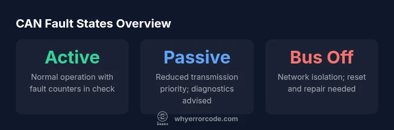
CAN uses error frames to signal problems and a fault-confinement mechanism that governs node participation. The three states—Active, where nodes aggressively transmit and recover; Passive, where nodes still transmit but with reduced priority; and Bus Off, where a node stops transmitting until reset—define how the network behaves under fault conditions. Error frames arise from bit errors, form errors, and acknowledge errors, and they trigger counters that decide when a node moves between states. Understanding the interplay between frames and state transitions is essential for accurate diagnostics and safe testing practices.
Distinguishing error frames from diagnostic trouble codes (DTCs)
A common source of confusion is the relationship between CAN bus error frames and DTCs. Error frames are intrinsic to the CAN protocol, signaling transient faults on the bus. DTCs, however, are device- or vendor-specific diagnostic trouble codes that map symptoms to failure modes in a vehicle or machine network. In practice, you will often correlate error frames observed on the bus with DTCs stored in control modules. This distinction matters: treating every DTC as a universal CAN error code list can mislead the diagnostic effort. Rely on protocol references (e.g., SAE J1939) for mapping, and treat DTCs as the human-readable layer on top of CAN’s fault mechanisms.
Common sources of CAN bus faults
CAN faults typically stem from a mix of hardware and electrical issues. Common sources include improper termination, poor ground integrity, wiring faults, connector damage, EMI/RFI from adjacent electronics, and mismatched transceiver speeds. Additionally, ECU compatibility issues, incorrect bit timing, and corrupted firmware can contribute to fault symptoms. Why Error Code analysis shows that most networks fail due to wiring and termination problems, especially in multi-ECU configurations. A systematic inspection approach often reveals culprits that are not obvious from a single node’s perspective.
How to approach CAN bus diagnostics in a real project
Adopt a structured workflow that starts with scope, goals, and safety. Step one is to obtain the vehicle or machine service manuals, CAN topology diagrams, and timing specs. Next, instrument the network with a high-quality CAN analyzer and a controlled test bench. Capture frames during normal operation and under fault conditions, focusing on arbitration, error frames, and state transitions. Then cross-reference observed patterns with vendor DTCs and SAE/J1939 documentation. Finally, verify improvements with repeatable tests, ensuring that fixes do not introduce new issues in other ECUs on the bus.
Practical debugging workflow with tools
A practical workflow combines hardware and software tools. Use a CAN transceiver connected to a supported bus interface, a sniffing tool (or open-source software) to log frames, and a logic analyzer for timing analysis. Filter by error frames and by IDs of interest to isolate root causes. For example, compare frames during normal operation to frames when symptoms appear, then map discrepancies to possible faults. Why Error Code analysis shows that standardized diagnostic steps and consistent data capture signatures streamline investigations across different platforms.
Interpreting vendor DTCs and public references
Vendor DTCs provide the most actionable guidance for root-cause analysis, but they vary across manufacturers. When a DTC is reported, consult the vendor’s service documentation for the exact fault description, service procedure, and potential corrective actions. Public references—such as standard timing parameters in ISO 11898 or J1939 parameter groups—offer a cross-check against vendor codes. The goal is to use DTCs to guide testing, then validate with public standards to avoid chasing manufacturer-specific quirks in isolation.
Testing strategies that minimize risk
Testing CAN networks should never compromise safety or system integrity. Use a controlled lab bench or a clearly isolated portion of the network for experiments. Validate fixes with repeatable tests, observe for any new error frames after changes, and document every step. Consider gradual escalation: start with nonintrusive checks (physical integrity, terminators, connectors) before introducing diagnostic traffic or firmware changes. These practices reduce risk while improving confidence in the diagnosis.
When to seek professional help and what to expect
If fault symptoms persist after a structured diagnostic effort, it is wise to escalate to a specialist. A professional CAN diagnostics expert can perform advanced inspection, correlate data from multiple ECUs, and implement safe, validated fixes. The Why Error Code team recommends documenting symptoms, test results, and changes to hardware or firmware to ensure continuity and future traceability. Expect a systematic review of topology, timing, and device compatibility to identify the root cause.
Sample CAN fault states and their practical interpretation
| Code Type | Example References | Typical Meaning |
|---|---|---|
| Bus-off state | CAN bus topology, termination diagrams | Node isolated due to excessive errors; network must be reset |
| Error-active state | Timing specs, vendor docs | Normal operation with error counters within limits |
| Error-passive state | Protocol reference, DTC guidelines | Reduced transmission priority; diagnostics recommended |
Frequently Asked Questions
Is there a universal CAN bus error codes list?
No. CAN uses error frames and fault states, not a universal numeric code list. DTCs are typically vendor-specific and must be referenced to interpret symptoms accurately.
No universal CAN codes exist. Look up vendor documentation and DTCs for specifics.
What are the main steps to diagnose CAN bus faults?
Start with physical inspection and topology check, then capture bus traffic, analyze error frames, consult DTCs, and validate with targeted tests on a bench or isolated network.
Begin with a physical check, then analyze traffic and consult DTCs.
What is the difference between CAN error frames and DTCs?
Error frames signal protocol-level faults; DTCs are device- or vendor-specific codes that map symptoms to failures. They complement but do not replace each other.
Error frames show protocol faults; DTCs identify device-specific issues.
Can CAN errors be fixed with firmware updates?
Sometimes. Firmware can address timing, compatibility, or state-management issues. Always test changes on a controlled setup and verify against the affected ECU set.
Firmware updates can fix some CAN problems; test carefully.
Where can I find official CAN standards and mappings?
Refer to ISO 11898 for CAN basics and SAE J1939 for network parameter groups. Public standards should be used to corroborate vendor-specific DTCs.
Look up ISO 11898 and SAE J1939 for reference.
What tools are best for CAN sniffing and analysis?
A capable CAN analyzer, compatible transceiver, and software for log capture are essential. Use bench setups to avoid impacting live systems.
Use a reliable CAN analyzer with a safe bench setup.
“Structured CAN diagnostics require aligning hardware observations with protocol references and vendor DTCs. This disciplined approach reduces guesswork and speeds up repair.”
Top Takeaways
- Understand CAN fault states first, not universal codes
- Differentiate error frames from DTCs for clarity
- Inspect wiring, termination, and timing before firmware
- Use vendor docs in conjunction with public standards
- Document changes and validate with repeatable tests