Car Error Code Sensor Troubleshooting Guide
Urgent, practical troubleshooting for car error code sensor issues. Learn common sensor types, how DTCs map to faults, safe at-home checks, a diagnostic flow, and when to seek professional help for reliable fixes in 2026.

Most likely causes are a failing sensor or a fault in its circuit. Quick checks include scanning for DTCs with a reliable OBD-II scanner, inspecting sensor connectors for corrosion or loose pins, and reseating the sensor harness. If the issue persists, follow the diagnostic flow below to isolate the exact fault.
Understanding car error code sensor basics
The term car error code sensor refers to any device that feeds data to the vehicle's engine control unit (ECU) and influences how the powertrain manages air, fuel, ignition, and emissions. When a sensor signal deviates from expected values, the ECU stores a diagnostic trouble code (DTC) and may illuminate the check engine light. Importantly, not every sensor fault will immediately cause a rough idle or a failed emissions test—some codes indicate borderline readings or intermittent faults. For the reader troubleshooting the car error code sensor, the goal is to determine whether the problem lies with the sensor itself, its wiring, or a downstream issue that alters the sensor reading. Sensor health is affected by age, heat, vibration, moisture, and contamination. Routine maintenance, such as cleaning connectors and replacing damaged wires, can prevent many false positives. The first step is to confirm the exact sensor involved by reviewing the freeze-frame data from your OBD-II tool and cross-checking it with the vehicle’s service manual. If you observe rapid fluctuations or readings outside the expected range, you are likely dealing with a faulty sensor or a compromised circuit.
Common sensor types and what they monitor
Several sensors are critical to modern engine management. The oxygen sensors monitor exhaust gas composition and help the ECU adjust fuel trim for optimal emissions. The mass air flow (MAF) sensor measures air entering the engine to help calculate the correct fuel amount. The manifold absolute pressure (MAP) sensor tracks intake pressure, while crankshaft position and camshaft position sensors determine timing references. Wheel speed sensors monitor rotation for ABS and traction control, and coolant temperature sensors inform warm-up schedules. Each sensor has a typical operating range; as components age or suffer contamination, readings drift and can trigger a fault code. When diagnosing, look for patterns: sensor-specific codes, intermittent readings, or codes that occur only after cold starts or during acceleration. Keep in mind that a failing sensor often manifests as a cascade of downstream symptoms, not just a single fault code. This section helps you map symptoms to likely sensors without jumping to conclusions.
How DTCs map to sensor faults
Diagnostic trouble codes provide clues about the sensor circuit rather than a definitive replacement. A code can point to the sensor, the wiring, the ground, the connector, or a related control module. General codes indicate broader issues, whereas manufacturer-specific codes may narrow to a particular sensor family. When a DTC appears, review freeze-frame data to see engine load, RPM, temperature, and sensor readings at the moment the fault occurred. This data helps differentiate a failing sensor from a wiring issue or a transient hiccup caused by a temporary condition, such as a sensor being momentarily out of spec due to a vacuum leak. Remember, multiple sensors can produce related codes if the root cause is wiring damage or corrosion. In practice, avoid blaming a part right away—follow the data-driven approach described here to confirm the fault before replacement.
Safe at-home checks you can perform
Safety first: always disconnect power and wear protective gear when working on a vehicle. Start with the basics: check the battery health and fuses related to the sensor circuit, then inspect the sensor connectors for corrosion, dirt, or loose pins. Reseat connectors firmly and clean any corrosion using a safe contact cleaner. Inspect the wiring harness for damaged insulation, pinch points, or abrasion and repair or replace damaged sections. If you can, compare sensor signals with the service manual specifications or a known-good vehicle. Clear any codes after performing checks and run a short drive cycle to see if the warning returns. If the check engine light recurs, proceed with the diagnostic flow below to isolate the fault more precisely.
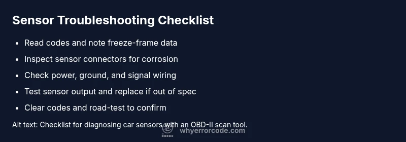
Diagnostic flow you can follow to isolate the problem
Start with symptom verification: confirm the fault code using your OBD-II scanner and check freeze-frame data. Next, test the sensor’s electrical circuit: verify power supply and grounding, and inspect the harness for continuity. If power and ground are solid, test the sensor output with a multimeter or oscilloscope where available. Compare readings to the manufacturer’s acceptable range; out-of-spec values indicate a faulty sensor or wiring, while normal values point to downstream issues. If you identify a faulty sensor, replace it and re-check the system. If wiring or grounding shows problems, repair or replace the affected section. After any repair, clear codes and perform a road test to confirm the issue is resolved. Always document findings for future maintenance to prevent repeat failures.
When to seek professional help and prevention tips
Some sensor issues involve complex diagnostics, special tools, or calibration procedures that require a trained technician. If the fault persists after inspecting and replacing suspected components, or if the vehicle exhibits drivability problems such as misfires, stalling, or poor acceleration, seek professional assistance. Prevention includes regular connector cleaning, corrosion inspection, and using quality replacements with proper torque and sealing. Avoid aggressive cleaning methods that damage seals or sensor faces, and schedule routine maintenance aligned with the manufacturer’s intervals. Keeping the engine bay dry and clean reduces contamination risk, while using OEM-recommended sensors minimizes mystery failures. Documenting fault history helps technicians diagnose faster in the future.
Steps
Estimated time: 60-90 minutes
- 1
Prepare safely and gather tools
Park on a flat surface and engage parking brake. Disconnect the battery to avoid shorts. Gather an OBD-II scanner, multimeter, service manual, and basic hand tools. Take photos of wiring before disconnecting anything.
Tip: Always disconnect the negative battery lead before handling sensor wiring. - 2
Read codes and freeze-frame data
Connect the OBD-II scanner and read the current and pending codes. Note freeze-frame data such as RPM, engine load, temperature, and throttle position at the time of failure. This helps narrow the suspect sensor.
Tip: Document the exact code and conditions; you’ll need it for later comparison. - 3
Inspect sensor and harness visually
Check connectors for corrosion, bent pins, or loose fitting. Wiggle the harness gently to feel for intermittent connections. Clean with an appropriate contact cleaner and reseat firmly.
Tip: Do not use excessive force on delicate sensor pins. - 4
Check power, ground, and signal circuits
With the battery connected, measure supply voltage and ground continuity at the sensor. If the readings are out of spec, repair the wiring or grounding path before replacing the sensor.
Tip: Keep measurements documented; a temp spike can mislead tests. - 5
Test sensor output (if possible)
Using the service manual, compare sensor output to expected values under different engine conditions. If the sensor is consistently out of range, replacement is warranted.
Tip: If you don’t have the right tool, substitution with a known-good part is risky; consult a pro. - 6
Replace sensor and validate
Install a new sensor, reconnect all harnesses, clear codes, and perform a test drive to confirm resolution. Recheck with the scanner for any residual codes.
Tip: Resetting the ECU may require a drive cycle to relearn sensors.
Diagnosis: Check engine light on with a sensor-related DTC or irregular sensor readings
Possible Causes
- highSensor itself is failing or drifting
- highWiring harness or connector damage or corrosion
- mediumPoor ground or ECU communication issue
- lowVacuum leaks, dirty intake, or external contamination
Fixes
- easyInspect and reseat sensor connectors; repair damaged wiring as needed
- mediumReplace the faulty sensor and recheck readings
- mediumRepair/replace wiring harness or ground connections to the ECU
- easyAddress external issues like vacuum leaks or intake contamination
Frequently Asked Questions
What is a car error code sensor?
A car error code sensor is a device that provides data to the vehicle's ECU to manage engine performance and emissions. When readings diverge from the expected range, the ECU stores a DTC and may illuminate the check engine light.
A car sensor is a device feeding data to the engine computer; a fault triggers a check engine light and a diagnostic code.
How do I know if the sensor really failed?
Compare readings to service manual specs and observe the symptom pattern. Intermittent codes and inconsistent sensor data typically indicate a failing sensor or wiring issue rather than a one-off glitch.
If readings are out of spec consistently or you see repeated codes, the sensor or its wiring is likely failing.
Can I drive with a sensor problem?
Driving with a sensor fault may affect performance and emissions, but many vehicles can be driven short distances for diagnosis. Do not drive aggressively or long distances; seek a safe inspection if powertrain behavior worsens.
You can drive slowly for a short distance, but avoid long trips; a professional check is recommended if symptoms persist.
What tools do I need to diagnose sensors?
An OBD-II scanner, a multimeter or oscilloscope if available, service manual specs, and basic hand tools. Having access to the vehicle's wiring diagram helps identify correct test points.
You’ll need an OBD-II scanner and basic testing tools; a service manual is extremely helpful.
When should I replace a sensor vs. fixing wiring?
Replace a sensor if it consistently reads out of spec under test conditions. If readings are near spec but wiring shows damage or poor connections, repair wiring first to avoid unnecessary part replacement.
If the sensor is clearly out of spec, replace it; otherwise repair wiring and retest.
Watch Video
Top Takeaways
- Diagnose rather than guess to avoid needless sensor replacements
- Check wiring and grounds as often as the sensor itself
- Use freeze-frame data to narrow the fault source
- Confirm repairs with a road test and re-scan
- When in doubt, consult a professional